How does KLD UT 18 hand wired amp work
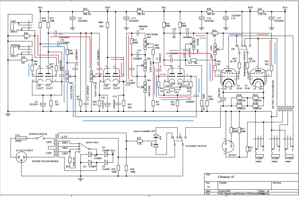
KLD UT18 1 8w hand wired amplifier based on VOX AC15, it has two channels controlling gain independently and can plug two guitar simultaneously. Two channels are: Lead and Normal. Below is sechmatic of UT18, the blue line represents the flow of signal of Normal channel, red line represents the flow of signal of Lead channel. |
 |
| Normal : V1B-V3-V4/5 The signal of Normal channel passes through classic gamma network comprised of a 1M (R39)grid leak resistor and an 47K(R36 ) effective grid-stopper resistance.Different with Marshall and Fender amp, the gride leak resistor R36 is 47K, not 68K as JCM 25 and Bassman 25, which let the more signal flows to grid of V1B. The V1B share a 1.5K(R1) cathode resistor and bypass capacitor 22UF(C1) with V1A, which doubles the current through it. According to Ohm's Law, the resistance needed to create the same cathode voltage doubles when only one tube is used, so the equivalent resistance for one triode is 3K. Only half the capacitor value is needed for the same bypass performance: 11 UF. This cooler bias gives earlier breakup and smoother sounding asymmetric distortion. After a stage amplified, the signal of normal channel passes through VR2 going to Long Tail Pair (LTP) Phase Inverter directly, then flows to Class AB power amp comprised by V4 and V5. |
| Lead: V1A-V2-V3-V4/5 The signal of Lead channel also passes through classic gamma network comprised of a 1M (R38)grid leak resistor and an 47K effective grid-stopper resistance.After passing through the first preamp V1A and VR1, it goes to the second preamp V2B, then to cathode follower V2A which supplies the tone stack with a low impedance signal. |
| Tone stack In order to compensate guitar amp pickups which has strong low middle emphasis and little high frequency response - overall a very muddy and muffled sound, tone stack provids compensation for the natural sound of a pickup - the middle pot simply boosts the pickup's normal 'middley' sound. The treble and bass pots do the opposite , boosting higher and lower frequency levels, leaving a notch in-between for middle freq tone. So with typical settings of a bit of bass, middle and treble, the overall tone equalization complements the natural pickup sound for a balanced response of lows, mids and highs. Comparing with tone stack control of Fender amp, Marshall amps are best at low-middle freq and crunchy rock tones, played at medium to high overdrive levels. Detail about tone stack, please watch How The Guitar Amp Tone Stack Works |
| The Long Tail Pair Phase Inverter:Works The Long Tail Pair (LTP) Phase Inverter (also called the cathode-coupled phase inverter) is the most popular phase inverter in guitar amplifiers due to its large output voltage swing and sweet overdrive tone. Unlike the non-amplifying cathodyne phase inverter used in many guitar amps the LTP phase inverter not only creates a dual mirror image signal stream but it also acts as a gain stage boosting the signal by about 1/4 of what two normal triode gain stages would. This added gain gives its output more voltage swing to drive big bottle power tubes to a fully distorted state. The LTP is a true differential amplifier and uses both halves of a dual triode tube (usually a 12AX7or 12AT7). R21 is the tail resistor that creates the relatively high voltage needed for the cathode follower function of the V3A's cathode. It also supplies a near constant current flow shared between the two cathodes--as current increases through the V3A's cathode the current decreases through the lower and vice versa. R11 is a standard bias resistor and creates a 1.2 volt difference between both tubes' grid and cathode. Its 1K2 ohm value shared between the two cathodes is the equivalent of each triode having a 2.4K ohm cathode resistor so the phase inverter is biased cold. R10 and R12 are simply grid leak resistors which leak off DC grid current to maintain a steady DC bias voltage between the grid and cathode. The plate load resistors R14 and R15 are same value 100K.The LTP circuit of UT 18 like PVA18. C21 and VR7 bridge over two outputs of LPT, which the high frequency signals of two reverse phase are counteracted, construct one high frequency tone filter. |
| Power amplifier:EL84 push-pull class AB The power amp stage of UT18 is almost same as Marshall TMB 18, only except the value of R24 little difference. R40 and R41(2K2) are grid stopper resistor which help tame oscillation of amp,and can reduce high freq tone in amp, but they need be within 10K. The cathode of power stage of UT18 is self bias, which has more sustain and dynamics but a spongier response particularly with bass notes (more sag). The cathode bias circuit of V4 and V5 is consisted by the C15 and R24. Because the vacuum tube is voltage amplify component that impandance is high, so the signal out of power tube are small currents with high voltage, which cannot drive low impedance coil of speaker and must transform them into big currents with low voltage. It is reason why tube amp need one expensive output transformer. Other question need pay attention, if the amp has not output load ( secondary coil of OPT open-circuit), it is equivalent to that the impedance of prime coil of output transformer is infinit, the prime coil of OPT would endured more than 1000v voltage caused transformer breakdown easily. Although UT18 is classical design, you can try to modify it still. It will help you understand principle of amp deeply, same time, you can obtain the tone you like more. |