How does KLD DC30 hand wired amp work
KLD DC30 30w hand wired amplifier based on Matchless DC30, it has two channels CH1 and CH2.The gain of two channels can be controlled independently and two guitars can be plugged into them simultaneously. Below is schematic of DC 30, the blue line represents the flow of signal of CH 1 Normal channel, red line represent the flow of signal of CH2 lead channel. |
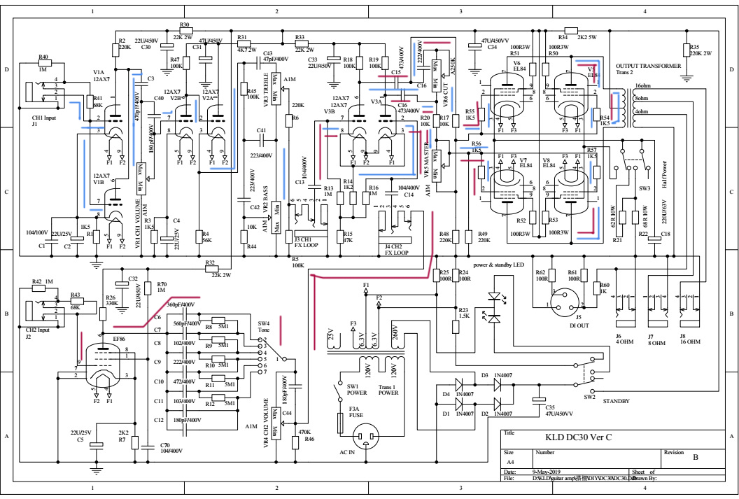 |
| CH2 : EF86-V3(LTP)-Power amp CH2 channel of DC30 provides six clean tones to amp. The signal of CH2 channel is labeled by red line on the schematic. After the signal of guitar inputs the classic gamma network comprised of a 1M (R42)grid leak resistor and an 68K(R43 ) effective grid-stopper resistance, it is amplified by EF86 tube then flows to six classes high-pass filter frequency selection net consisted by capacitor of C6-C12 and one six position switch(SW4). There is only one stage preamp in the CH2 which gain is controlled by VR4.In order to absorb the current shocking of switch SW4, there are five high value resistors R8-R12( 5M1) paralleling with the capacitors in this net. Out of this frequency network, then signal pass through Long Tail Pair (LTP) Phase Inverter to the power amp stage directly. |
| CH1 : V1-VR1-V2-Tone stack-V3(LTP)-Power amp The CH1 channel is based on VOX AC 30 top boost.The signal of CH1 is labeled by blue line in the schematic. The input circuit of CH1 is still the classic gamma network comprised of a 1M (R40) and a 68K(R41). Difference with AC 30, the first preamp of DC 30 is comprised of paralleling the two amps of the first tube 12AX7(V1A and V1B), which boost the gain of input and increase the input current. The gain of CH1 is controlled by VR1.CH1 has two stages of preamp consisted by V1 and V2B. The tone of CH1 is controlled by a tone stack circuit( only Treble and Bass) .Before the tone stack, there is a cathode follower consisted of V2A, which drive the tone stack by lower output impedance. |
| Tone stack In order to compensate guitar amp pickup low middle emphasis and little high frequency response - overall a very muddy and muffled sound, tone stack provides compensation for the natural sound of a pickup - the middle control simply boosts the pickup's normal 'middley' sound. The treble and bass controls do the opposite, boosting higher and lower frequency levels, leaving a notch in-between for middle freq tone. So with typical settings of a bit of bass, middle and treble, the overall tone equalization complements the natural pickup sound for a balanced response of lows, mids and highs. Detail about tone stack, please watch How The Guitar Amp Tone Stack Works |
| The Long Tail Pair Phase Inverter V3 The Long Tail Pair (LTP) Phase Inverter (also called the cathode-coupled phase inverter) is the most popular phase inverter in guitar amplifiers due to its large output voltage swing and sweet overdrive tone. Unlike the non-amplifying cathodyne phase inverter used in many guitar amps the LTP phase inverter not only creates a dual mirror image signal stream but it also acts as a gain stage boosting the signal by about 1/4 of what two normal triode gain stages would. This added gain gives its output more voltage swing to drive big bottle power tubes to a fully distorted state. The LTP is a true differential amplifier and uses both halves of a dual triode tube (usually a 12AX7or 12AT7). R15 is the tail resistor that creates the relatively high voltage needed for the cathode follower function of the V3A's cathode. It also supplies a near constant current flow shared between the two cathodes--as current increases through the V3A's cathode the current decreases through the lower and vice versa. R14 is a standard bias resistor and creates a 1.2 volt difference between both tubes' grid and cathode. Its 1K2 ohm value shared between the two cathodes is the equivalent of each triode having a 2.4K ohm cathode resistor so the phase inverter is biased cold. R13 and R16 are simply grid leak resistors which leak off DC grid current to maintain a steady DC bias voltage between the grid and cathode. The plate load resistors R19 and R18 are same value 100K. C16 and VR6 bridge over two outputs of LPT, which the high frequency signals of two reverse phase are counteracted, construct one high frequency tone filter. The LTP of DC30 is standard circuit. |
| Power amplifier: push-pull class AB 4XEL84 The power stage of DC30 is push-pull class AB amplifier consisted of four EL84 tubes.These four EL 84 tubes are divided into two pairs. The pair of V5 and V8 is consisted of one circuit of push-pull class AB amp. The pair of V6 and V7 is other one.Two pairs are paralleled mutual. Certainly, these four tubes can be divided by up an down groups, V5 and V6 is one group, it is Class A amp, V7 and V8 is another, it is Class B amp.These four tubes must be paired totally. The cathode of power stage of DC30 is self bias also, which has more sustain and dynamics but a spongier response particularly with bass notes (more sag). The cathode bias circuit is consisted by the C18 and R21,R22. Because the vacuum tube is voltage amplify component that impandance is high, so the signal out of power tube is small current with high voltage, which cannot drive low impedance coil of speaker and must transform them into big current with low voltage. It is reason why tube amp need one expensive output transformer. Other question need pay attention, if the amp did not connected with load ( secondary coil of OPT open-circuit), it is equivalent to that the impedance of prime coil of output transformer is infinit, the prime coil of OPT would endured more than 1000v voltage caused transformer breakdown easily. |